|
 |
 |
 |
 |
 |
 |
|
||
|
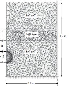
1.Tunneling a) A study on the effects of overlying soil strata on the stresses developing in a tunnel lining Shield tunnel lining in soft ground is usually designed based on empirical and analytical methods. These methods are convenient and easy to use; however, they are based on simplifying assumptions related to soil homogeneity around and above the excavated tunnel. The effects of overlying stiffer layers on the tunnelling induced settlement has been investigated by several researchers and was found to significantly influence ground movements. The aim of this study was to evaluate the effects of overlying stiff layers above a tunnel excavated in soft ground on the stresses developing in the tunnel lining. Laboratory investigation was conducted to study how the presence of these layers influence bending stresses in a model tunnel constructed in soft clay and overlain by a coarse sand layer located at different heights above the tunnel. Validation using the experimental results, elasto-plastic finite element analyses are then performed to explain the role of the relative stiffness between the overlying layer and the soft soil deposit hosting the tunnel. Depending on the thickness and location of the overlying stratum, the presence of a stiff layer above the tunnel can have a significant impact on the stresses developing in the tunnel lining.
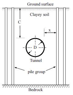
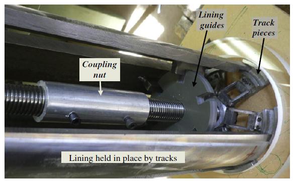
b) Investigation of Tunnel-Soil-Pile Interaction in Cohesive Soils Underground tunnels are considered to be a vital infrastructure component in most cities around the world. Careful planning is always necessary to ensure minimum impact on nearby surface and subsurface structures. An experimental investigation was carried out to examine the effect of existing piles installed in cohesive soil and extended to bedrock on the circumferential stresses developing in a newly constructed tunnel supported by a flexible lining system. A small scale testing facility was designed and built to simulate the process of tunnel excavation and lining installation in the close vicinity of preinstalled model piles. Lining stresses were measured for different separation distances between the lining and the existing piles Consistent decrease in the lining load was observed when the piles are located within a distance of one tunnel diameter from the tunnel. The results presented in this study indicated that measuring the lining response near existing pile foundations may be used to evaluate the extent of the interaction between the lining and the surrounding piles.
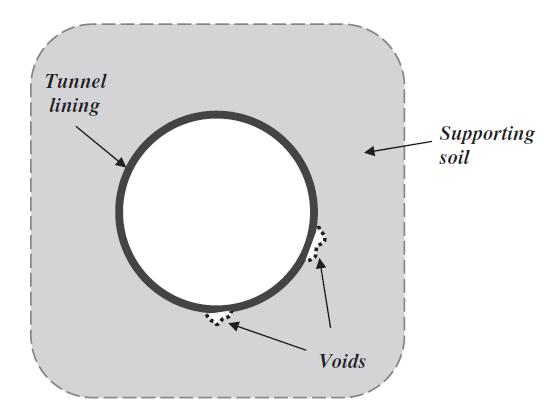
c) An experimental study of the effect of local contact loss on the earth pressure distribution on existing tunnel linings This study presents the results of the experimental investigation that has been conducted to examine the effect of local contact loss between a tunnel lining and the surrounding ground on the earth pressure distribution acting on the tunnel liner. An experimental setup has been designed using a mechanically adjustable tunnel model to simulate the initial lining pressure that results from shield tunnelling. A local separation between the lining and the surrounding soil was introduced at different locations around the tunnel and the changes in contact pressure were measured. Results indicated significant changes in earth pressure in the close vicinity of the area that has experienced the contact loss. The changes in earth pressure differed greatly depending on the location of the induced separation. When located at the invert and haunches results showed an increase in pressure by about 28%, whereas a pressure decrease of about 75% was measured immediately above the separated section when located at the springline. The above results suggest that the presence of a small lining area that is not in direct contact with the surrounding ground can have a significant impact on the performance of the tunnel lining.
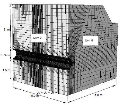
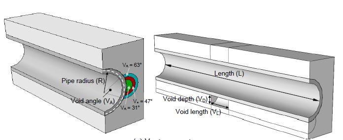
2. Rigid Pipes a) The effect of erosion voids on the performance of rigid pipes The design of buried pipes requires the consideration of full contact between the pipe and the surrounding soil. After installation, loosening of surrounding soil may occur with time leading to the development of erosion voids next to the pipe wall. This phenomenon is known as ground support loss and has been known to cause pipe damage and in some cases has led to complete failure. Previous studies were limited to numerical modeling using two-dimensional analyses. The main objectives of this research program are: (1) To experimentally study the impact of erosion void located next to the pipe wall on the changes in earth pressure acting on the pipe and (2) to develop a three-dimensional numerical model to investigate the effect of void size on the changes in earth pressure and stresses in the pipe wall due to the introduction of a finite void around the pipe.
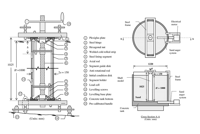
3. Dams a) Assessing the role of inherent anisotropy on the liquefaction potential of tailings impoundments Tailings impoundments are important facilities in the mining industry. The safety of these impoundments is not only related to the impact of failure on mine production but also related to peoples lives downstream of the facilities and the surrounding environment. A catastrophic release of a large amount of tailings could lead to long term environmental damage with huge cleanup costs. Failure of tailings dams may occur due to several reasons including the instability of the raised embankment, overtopping, and static/cyclic liquefactions. 4. Cylinderical Shafts a) Active earth pressure on cylindrical shafts in soft ground Experimental investigations on model shafts have been very useful in explaining the soil arching phenomenon and the earth pressure acting on a shaft lining. Several studies have been conducted to measure the earth pressure distribution owing to the installation of model shafts in granular material. One of the key challenges in developing a shaft apparatus is to simulate the radial deformation of the ling and the associated soil movement during construction. This study focuses on the continuous measurement of contact pressure distribution on a shaft lining using flexible pressure sensors. The role of soil type and ground movements is also evaluated.
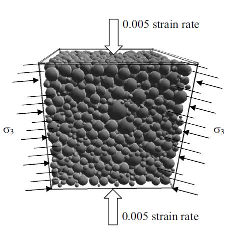
5. Numerical Modeling a) Algorithm to Generate a Discrete Element Specimen with Predefined Properties The discrete element method is a powerful numerical tool in simulating the behavior of granular materials. It bridges the gap between continuum mechanics and physical modeling investigations. In spite of the significant achievements to date, some major problems are yet to be solved including the development of realistic large-scale models with initial conditions similar to those encountered in real problems. This paper introduces a computational method to generate a large-scale packing with predefined porosity and grain-size distribution in three-dimensional space based on a small initial sample packing. The developed method is implemented into an pensource computer code and used to generate specimens with known properties. The results showed that, under static condition, specimens generated using the proposed algorithm exhibited realistic behavior suitable for geotechnical applications. In addition, the controlled structure of the initial sample packing is successfully transferred to the final packing
b) An efficient finite–discrete element method for quasi-static nonlinear soil–structure interaction problems
c) The effect of erosion voids on existing tunnel linings Erosion voids may develop around buried infrastructures due to several reasons including water infiltration into leaking joints, dissolution of Karst limestone, and dynamic loading caused by construction related activities. This study evaluates the effect of erosion voids developing in the close vicinity of existing tunnels on the circumferential stresses in the lining. A series of simplified void geometries are defined beside and under the lining. Elasto-plastic finite element analyses are performed to study how those voids influence thrust forces and bending moments in the lining. The role of other factors such as the lining flexibility and in situ stress conditions is also investigated. Depending on the flexibility ratio between the lining and the surrounding soil, the void size can have a significant impact on the circumferential stresses in the tunnel lining. A void under the invert leads to decrease in the magnitude of bending moment, and for large void size, the moments can reverse sign. This preliminary study suggests that efforts to arrest the growth of erosion voids at the invert and springline should be made before the voids reach this size. All results presented are theoretical in nature, and physical testing is needed to evaluate the performance of these calculations. d) Application of a multilaminate model to simulate the undrained response of structured clay to shield tunnelling A constitutive model based on the multilaminate framework has been implemented into a finite element program to investigate the effect of soil structure on the ground response to tunnelling. The model takes into account the elastic unloading-reloading, inherent and induced anisotropy, destructuration, and bonding effects. The model is successfully calibrated and used to investigate the undrained response of structured sensitive clay in the construction of the Gatineau tunnel in Gatineau, Quebec. Numerical results were compared to the field measurements taken during tunnel construction. To improve the performance of the numerical model, an implicit integration algorithm is implemented and proven to be very effective when coupled with the multilaminate framework as compared to the conventional explicit integration methods. The effect of different soil parameters including bonding and anisotropy on the tunnelling induced displacements and lining stresses is also examined using a comprehensive parametric study. The results indicated that soil bonding and anisotropy have significant effects on the shape of the settlement trough as well as the magnitudes of surface displacements and lining stresses induced by tunnelling.
|
|
|